Derating
Introduction
A brief overview of the importance of derating has been provided here, along with a sample determination of requirements calculations using Quanterion’s QuART-ER derating calculator and a description of the Stress-Derating Spreadsheet Calculator – SD-18. This topic is also covered in the Quanterion-authored Reliability Information Analysis Center (RIAC) publication “System Reliability Toolkit” and is included as a topic in Quanterion’s “Reliability 101 – Introduction to Reliability Engineering” training course.
What is derating?
The practice of limiting electrical, thermal and mechanical stresses on parts to levels below their specified ratings is called derating. MIL-STD-721C offers the following definitions of derating:
- Using an item in such a way that applied stresses are below rated values
- The lowering of the rating of an item in one stress field to allow an increase in another stress field
If a product is expected to operate reliably, one of the contributing factors must be a conservative design approach incorporating realistic derating of parts. The failure rate of an item is dependent upon the proximity of the applied stress on that item to its maximum allowable stress (“strength”). As the stress on a component increases, its failure rate generally increases. For example, one rule of thumb is that the previous failure rate is expected to double for every 10°C rise in temperature. Another guideline is that a 50% derating can decrease the failure rate by approximately 30%. (These statements are very general in nature. The impact of stress on any given component may vary significantly from these guidelines.)
Environmental and operational stresses
The stresses to which an item is subjected usually fall into one of the following categories:
- Environmental stresses
- Operational stresses
Examples of environmental stresses include temperature, humidity, vibration, temperature cycling, etc. Operational stresses include voltage, current, power dissipation, dynamic loading, etc. Components experience operational stresses during operation only, while environmental stresses can be experienced at any time, including times of dormancy. Operational stresses may also influence environmental stresses. For example, power dissipation typically results in a rise in a component’s case and/or junction temperature.
The purpose and logistics of derating
The importance of derating stems from the very nature of stress and strength. It is common to consider stress and strength (and hence “stress ratio”) to be point values. For example, consider a tantalum capacitor with an applied working voltage of 9V. If the maximum rated voltage (“strength”) is 10V, then the stress ratio can be calculated as:
![]()
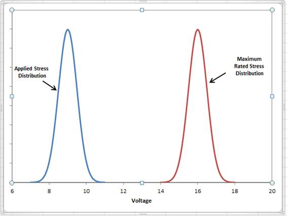
If only the point values are considered, it might be concluded that the design is adequate since the applied stress is less than the maximum rated stress (stress ratio < 1.0). However, the nature of stress and strength is such that variation exists around these estimates. Sources of variation for the stress may include power supply voltage, output voltage of any voltage regulators used to generate power rails, ripple due to inadequate decoupling, etc. Likewise, variation exists around the maximum rating (strength) due to various factors, including impurities in the dielectric, poor control of dielectric thickness, temperature variation, etc. Figure 1 illustrates the case where some degree of variation, modeled by a normal distribution, exists around the applied and maximum rated voltages in the above example.
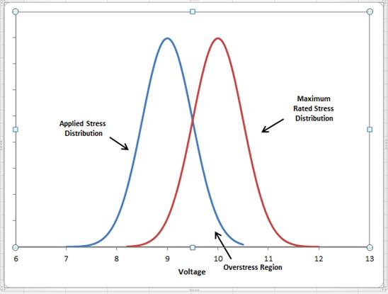
Figure 1: Variation Example – Mean Stress = 9V & Max Rating = 10V
It is evident that while the nominal maximum rating is greater than the nominal stress, there exists a region where the distributions overlap and the stress can actually exceed the true maximum rating and lead to part failure. This region is referred to as the ‘Overstress Region”. If the distributions and variance are known, then the area of this region can be estimated (refer to Reliability Que: Stress Strength Interference Analysis). The area of this interference region is the probability of failure. The addition of margin between the applied stress and maximum rating will reduce the overlap of the distributions and, hence, decrease the probability of failure. This margin between the applied and maximum rated stress is what is commonly referred to as “derating”.
For example, suppose in the application above, the 10V capacitor was replaced in the design with a part rated at 16V. In this case, the nominal stress ratio would be 9V/16V = 0.5625 or 56.25%. Assuming the same variation around the applied and maximum rated stresses as in the previous example, the distributions would be separated enough that the stress/strength overlap would be nonexistent. In this case, an overstress condition would be highly unlikely to occur (although the part could still fail due to other reasons). The distributions for the modified example are shown in Figure 2.

Figure 2: Variation Example – Mean Stress = 9V & Max Rating = 16V
Unfortunately, it is often the case where the variance, or even the type of distribution, is not known. In these cases, estimating the probability of failure is difficult. However, it will always be the case that the addition of margin between the applied stress and maximum rating (strength) will reduce the overlap of the distributions and, hence, decrease the probability of failure.
The derating requirements that are imposed on a design are dependent upon a number of factors. These factors include reliability challenge, ease of repair, safety, size and weight, and life cycle. The environment in which a design will be operated should also be considered. Conditions favoring less stringent derating requirements include:
- Proven design, achievable with standard parts and circuits
- Easy to access and repair
- Routine safety program – no potential costly system damage, injury or loss of life
- No significant design limitations
- No unusual spare parts costs expected
- Relatively benign operating environments
Conditions favoring stricter derating requirements include:
- State-of-the-art design with difficult reliability requirements
- Repair impossible (space designs), expensive or require high skill level
- Failure could result in loss of life, loss of mission or costly system damage
- Severe design limitation requiring new concepts
- Unique spares or complete substitution required
- Severe operating environments
Derating resources
“Electronic Derating for Optimum Component Reliability”
Introducing the second edition!

“Electronic Derating for Optimum Component Reliability: Second Edition” is a modern electronic component derating guideline designed to maximize the reliable application of the components in electronic equipment. It includes an introduction to part stress derating and general information relative to part derating theory and definitions, and updated electronic component derating guidelines.
Learn more about “Electronic Derating for Optimum Component Reliability.”
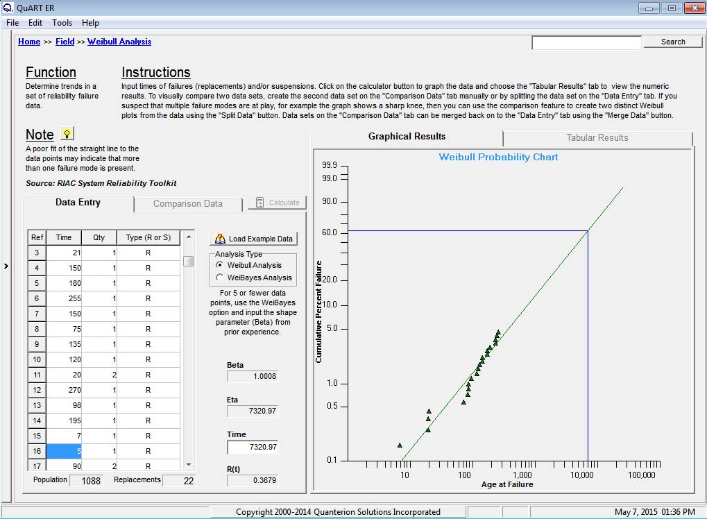
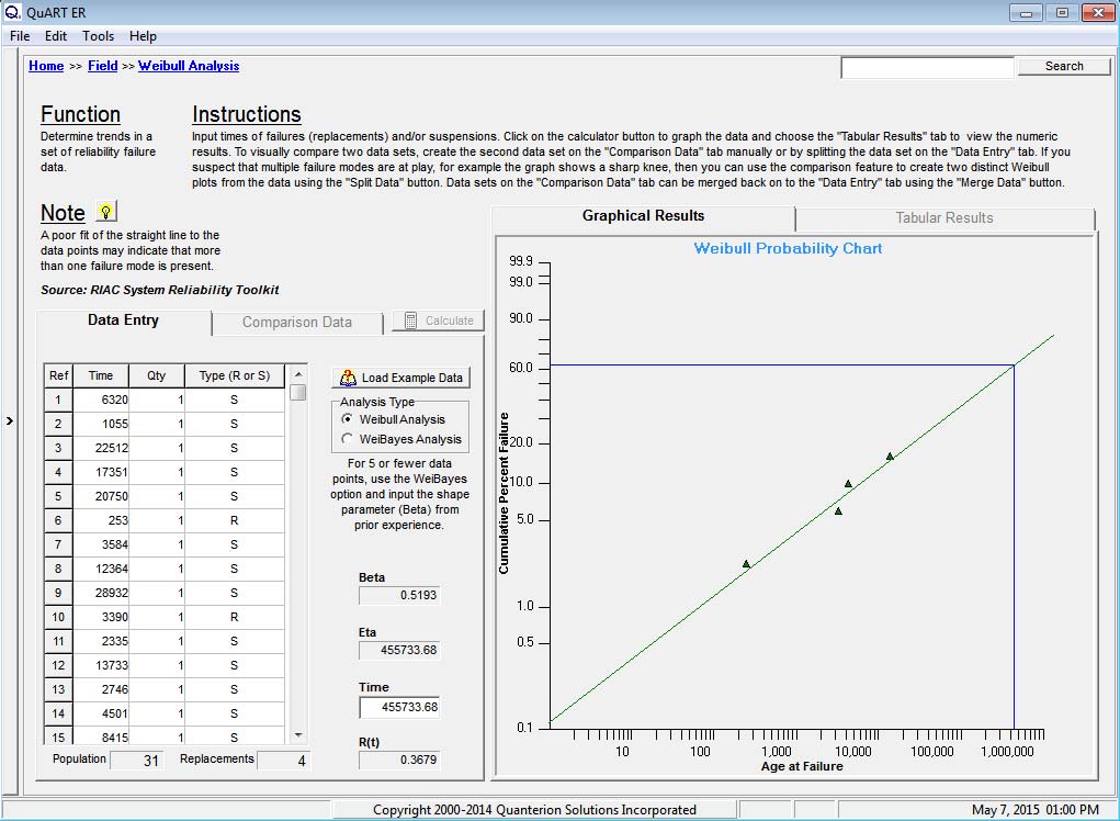
Quanterion Automated Reliability Toolkit – Enhanced Reliability (QuART-ER) and QuART-PRO
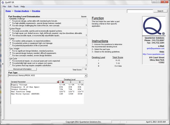
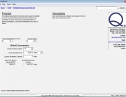
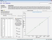
Figure 4: QuART-ER Derating Tool
The Derating function in the Quanterion Automated Reliability Toolkit – Enhanced Reliability (QuART-ER) and QuART-PRO tools can be used as a guide to define appropriate derating requirements. First, the part derating level must be determined. QuART-ER and QuART-PRO allow for the possibility of three derating levels, with Level 1 being the most severe, followed by Levels 2 and 3. The tools provide a list of questions pertaining to five subject areas, including reliability challenge, system repair, safety, size & weight, and life cycle. A score is assigned to each of the answers, which is then totaled. A total score of 11-15 results in a recommendation of derating Level 1; 7-10 corresponds to Level 2; and 6 or less corresponds to Level 3. Once the derating level is determined, the appropriate derating requirements for a given component type can be determined from the “Part Type” drop-down menu. For example, the derating requirements for a “Microcircuit, Memory/PROM MOS” device are shown in Figure 3.
The answers provided to the “Part Derating Level Determination” questions resulted in a total score of 12 and, therefore, a recommendation of Level 1 requirements.
Stress-Derating Spreadsheet Calculator – SD-18 Derating Standard
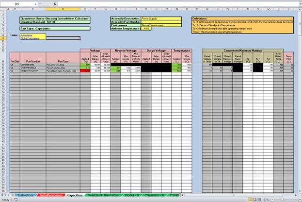
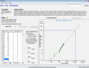
Figure 5: Stress-Derating Spreadsheet Calculator Tool
Quanterion Solutions’ Stress-Derating Spreadsheet Calculator – SD-18 Derating Standard is an Excel-based software tool that allows the user to easily determine if a design is in compliance with the derating guidelines presented in NAVSEA SD-18 Part Requirement and Application Guide. After selecting the application environment and entering the ambient baseline temperature, the user then enters components from a Parts List or BOM onto the appropriate commodity worksheet. After supplying part type identification, rating and application data, the Stress-Derating Spreadsheet Calculator determines the relevant derating requirement and indicates through a simple Green/Red color scheme, whether or not a parameter is in compliance with the standard. Critical part type data entry is drop-down menu driven, and all user accessible data entry fields are easily identifiable. A screen-shot of the ‘Capacitors’ worksheet is shown in Figure 4.
References
“Electronic Derating for Optimum Performance”, RIAC, 2000
SD-18 “Parts Requirements and Application Guide”, NAVSEA,http://www.navsea.navy.mil/nswc/crane/sd18/default.aspx (accessed 4/12/2013)
GEIA-STD-0008 “Derating of Electronic Components”, 2011
TE000-AB-GTP-010 Rev 1 Change A “Parts Derating Requirements and Application Manual for Navy Electronic Equipment”, NAVSEA, 1991
AS-4613 “Application and Derating Requirements for Electronic Components,” NAVAIR, 1976
MIL-STD-975M, Notice 2 (NASA) “NASA Standard Electrical, Electronic, and Electromechanical (EEE) Parts List (17 MAR 1995)
Find Quanterion Solutions on social media to access more reliability engineering information, resources, and more.